Emergency Kill Switch
Description
There are times when it seems important to be able to cut off the Mule
quickly. One of those times is when I'm loading the Mule in the back of
the truck as I walk it up the ramp. Another is when I am driving from the
walking position in the mountains. There is very little flat ground so the
mule is going sideways along the ridge or actually climbing up fairly
steep grades, often with a sizable load.
This project is to describe how I implemented an emergency kill switch to
cut off the engine in the possibility something goes wrong while operating
in these precarious conditions. This solution allows a lot of flexibility
in the positioning of the switch in relation to the mount. It is just one
possibility but hopefully it will spark other implementations.
ONE VERY IMPORTANT NOTE: This device should always be tested after
installation and before you may need it!
Design Considerations
The switch has to be stable, operable at almost any angle and RELIABLE!
I finally thought about the emergency kill switches used on boats, jet
skis, ATV's etc. This solved the reliable part, Now on to the mounting. I
wanted to be able to remove the switch when using the Mule under normal
conditions but it had to be stable. After poking around in my "junk" (
Fred Sanford would be proud. ), I found a couple different kinds of gun
mounts for ATVs which I felt could be reused as temporary mounting
brackets when necessary.
Materials
NOTE: BOLD text are hyperlinks which were valid at posting.
- 1 1/4" x 1/8" x 4 1/2" Aluminum flat stock
- 2 - 4-40 x 3/8" Flat head machine screws
- 3/8" x 16 x 1 1/4"" Machine screw ( usually comes with the Grip mount )
- 3/8" Flat washer
- 3/8" Split lock washer
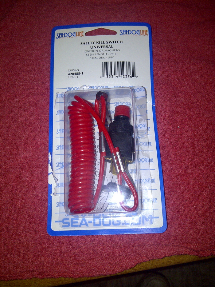
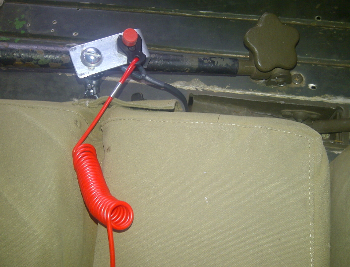
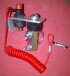
- Emergency Kill Switch ( Universal Kill Switch SeaDog Line - See Picture 1
)
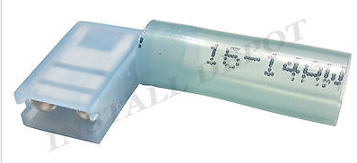
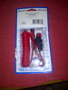
- 2 - Right Angle Wire Connectors ( Heat Shrink Flag Terminal Right Angle Wire Connector - See Picture 2.
)
- Wire Conector ( Connector Set Polarized SeaDog Line Or SeaDog 2 Pin Polarized Electrical Connector )
- 16 or 18 Gage Wire
- Heat Shrink Tubing
- 1/2"
- 3/8"
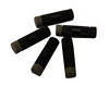
- 1/4" ( Roll - See Picture 3. )
- 1/8"
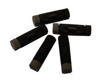
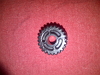
- 2 - Posi-tap Connectors, 12-18 Gauge Wire ( See Picture 4. )
- Coleman Fin Grip mount. ( one of the following links below )
OR
Make something similar.
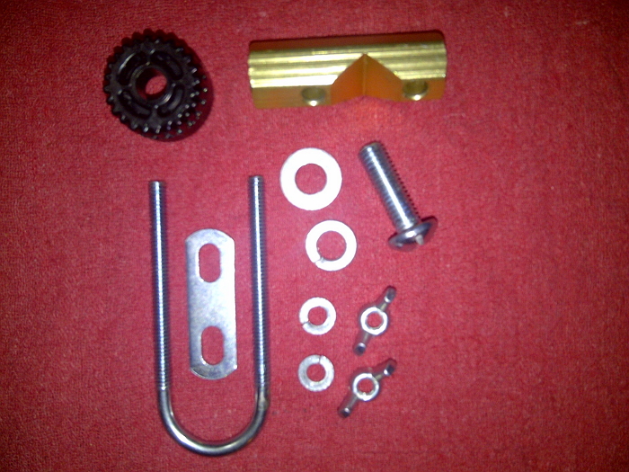
- SINGLE FIN GRIP PRO HANDLEBAR RACKS ( Option A -
See Picture 5 )
- 2 - 1/4" Wing nuts
- 2 - 1/4" Split lock washers
- 1/4" x 1-1/8" x 2" U-Bolt ( The supplied U-Bolt is usually too
narrow )
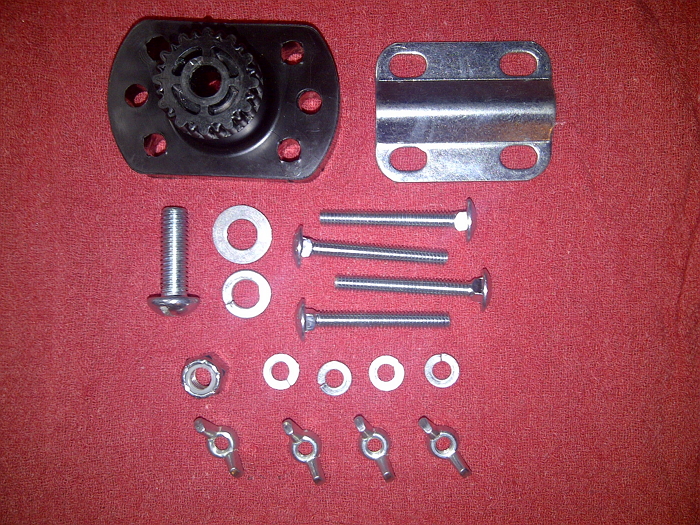
- FIN GRIP PRO RACK SINGLE ( Option B - See
Picture 6 )
- 4 - 1/4" Wing nuts
- 4 - 1/4" Split lock washers
- 4 - 1/4" x 2" Carriage bolts
- 3/8" x 16 Nylon lock nut ( usually comes with the Grip mount )
Tools
- Hacksaw or Band-saw
- Drill
- 5/8" Drill Bit
- 3/8" Drill Bit
- 4-40 Tap w/#43 bit
- Some way to bend the aluminum flat stock, i.e. Vise, Brake, etc.
- Wire Cutters and Strippers
- Soldering gun, solder and flux
- Heat gun or Torch
Steps
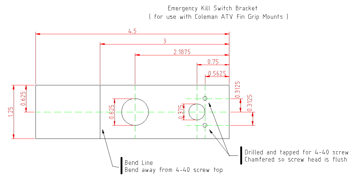
Refer to Figure A for steps 1 thru 7 below:
- Cut the Aluminum bar to length.
- Use a scribe and mark all the layout lines.
- Center punch the 4 drill points.
- Drill the 4 holes.
- Tap the 2 small holes for the 4-40 screws.
- Chamfer drill the 2 small holes so the 4-40 screws are flush with the
surface.
- Bend the bar at the indicated mark 90 degrees.
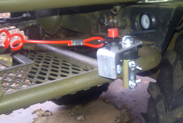
- Loosely mount the switch in the 5/8" hole in the bracket.
- Determine where you want to mount the switch and attach the mount.
- Orient the bracket in the desired position and screw the two 4-40
screws into the bracket.
- Screw the 3/8" screw with flat and lock washers through the bracket
into the mount and tighten.
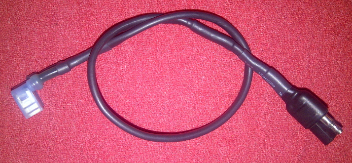
- Prepare the plug wire that will connect to the original kill switch. ( Refer to pictures 9 and 10 )
- Under the Mule, make the connections from the plug wire to the Magneto wires using Posi-tap Connectors. ( See Figure B for wiring diagram and Picture 4 for Posi-Tap Connector. )
- Determine how long the wire needs to be from the switch to the just
finished connector and cut to length.
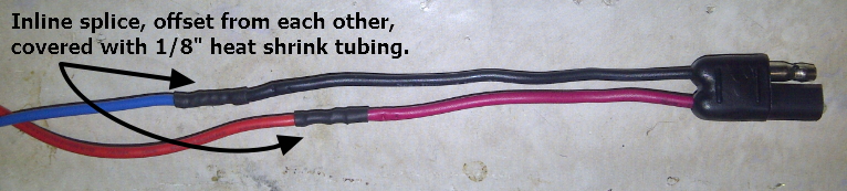
- Connect the mating plug to the the wires. Offset the connections by ~
1". I use a Western Union splice, solder and cover with heat shrink
tubing. ( Refer to pictures 9 and 10 )
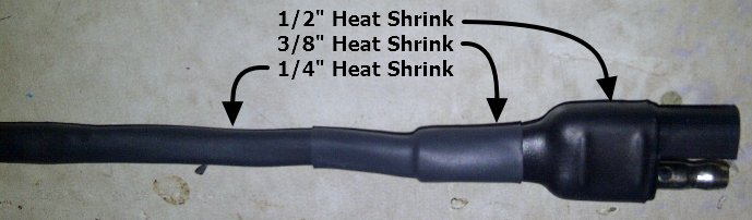
- Slide the 1/4" heat shrink tube the length of the wire, also slide the 3/8" and 1/2" lengths of heat shrink tubing on the wire.
- Solder or crimp the 90 degree wire connector to the opposite end of the wires.
- Arrange all the heat shrink tubing and complete the Switch Wiring Harness. ( See Picture 11. )
- Route the wire and align the switch terminals so the flag terminals
line up and tighten the switch nut.
- Push the flag terminals onto the M terminals of the switch and plug
the 2 halves of the connector together.
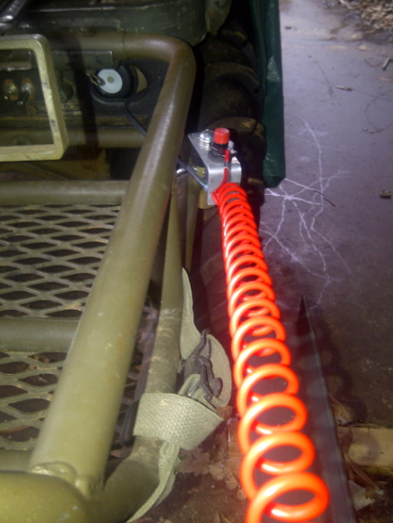
- Make sure the Clip with the lanyard is attached to the switch.
- Start the mule, pull on the lanyard until the clip comes off the
switch and the Mule should stop running.
Pictures
Picture 1: Universal Emergency Kill Switch - SeaDog ( Click on image
to enlarge. )

Picture 2: 3M BLUE 16-14 GAUGE HEAT SHRINK FLAG TERMINALS RIGHT ANGLE WIRE CONNECTOR (
Click on image to enlarge. )
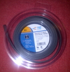
Picture 3: 1/4" x 8' Heat Shrink Roll (
Click on image to enlarge. )
Picture 4: Posi-tap Connectors, 12-18 Gauge Wire (
Click on image to enlarge. )
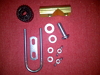
Picture 5: Parts for Single Fin Grip Pro Handlebar Rack - Option A (
Click on image to enlarge. )
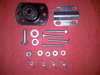
Picture 6: Parts for Fin Grip Pro Rack Single - Option B ( Click on
image to enlarge. )
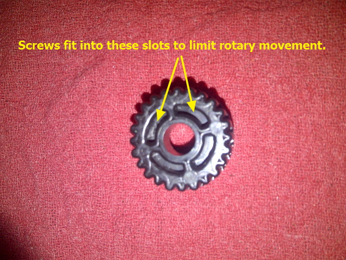
Picture 7: Coleman Fin Grip Mount top detail ( Click on image to
enlarge. )
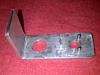
Picture 8: Finished Mount Bracket ( Click on image to enlarge. )
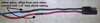
Picture 9: Splicing wires to connector ( Click on image to enlarge. )
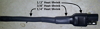
Picture 10: Protecting connector wires from breaking ( Click on image to enlarge. )

Picture 11: Switch Wiring Harness ( Click on image to enlarge. )